What it takes to fly a circuit board on a stratospheric balloon
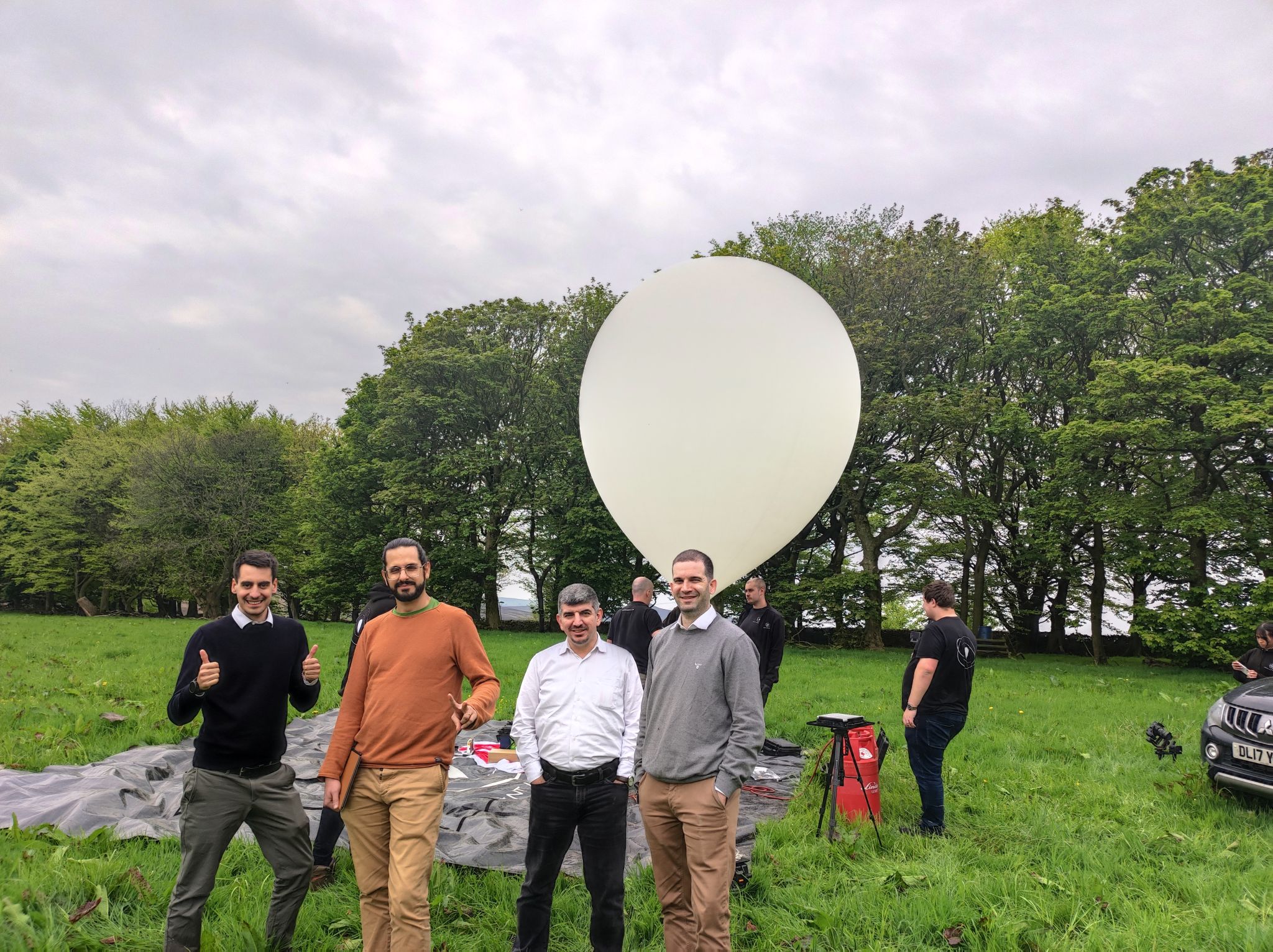
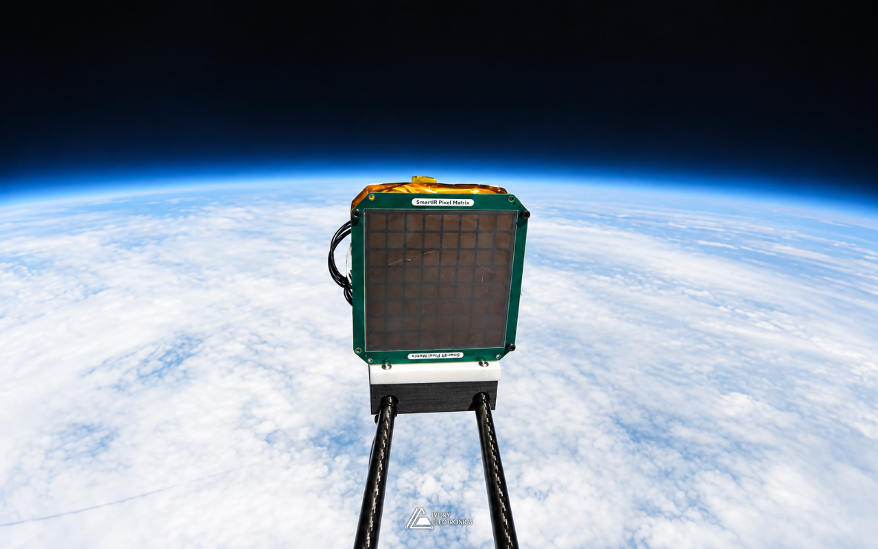
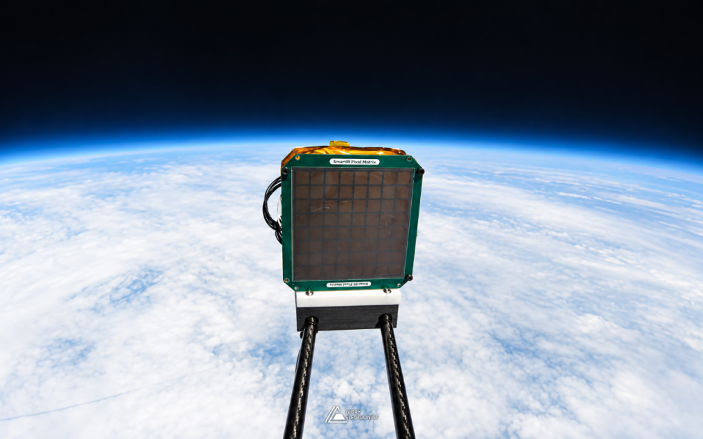
On 1 May 2023, a square green tile rode a weather balloon up through the atmosphere until the sky behind it turned black and the Earth’s horizon curved beneath it. The tile was SmartIR’s graphene smart radiator, and the flight was the company’s Mission 1, launched in collaboration with Sent Into Space. Behind the tile sat the circuit board that drove it, designed by our CEO, Dr. Daniel Melendrez, together with Prof. Coskun Kocabas of the University of Manchester. This post is about that board, and about what changes when the hardware you design is going to leave the ground.
The mission, in public terms
SmartIR is a University of Manchester spin-out developing graphene-based adaptive radiators: thin, lightweight devices that control how a surface emits heat, electronically and with no moving parts. That capability matters in space, where, as the ESA Business Incubation Centre UK has noted, satellites can experience temperature variations of more than 400 °C. Before orbit comes the stratosphere, and Mission 1 was the first time the technology left the lab.
Our part was the electronics that sat between the payload’s controller and the multi-pixel tile. We will leave the device physics to SmartIR. What follows is the electronic design perspective: what the board had to be, and what the flight environment demanded of it.
The requirements came down to a few words:
- One interface. A single compact wire-to-board connector carries power, a two-wire digital bus and one control signal from the controller. Every extra wire in a flight harness is another thing to route, secure and fail.
- Local intelligence. Drive generation happens on the board itself, so the controller sends commands, not dozens of individual signals.
- Fixed configuration. Options are set with solder jumpers, which have no moving parts to shift under vibration.
- A safe power-up. The drive electronics start in a known, inactive state and do nothing until software configures them.
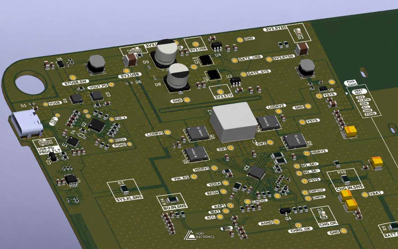
The result is a six-layer board, about ten centimetres square, with fewer than 30 footprints, logos included. The revision code on the silkscreen reads Rev. A-0323: designed in March 2023, flying by May.
Challenge 1: The cold
In the International Standard Atmosphere, air temperature falls to about −56.5 °C at the tropopause and stays there for kilometres. That is below the −40 °C lower limit of the industrial temperature grade that most commercial parts are specified to. For a balloon payload, this means component ratings are the start of the conversation, not the end:
- Passives drift. Common ceramic dielectrics lose a significant share of their capacitance at low temperature. X7R, for example, is only specified to within ±15% across −55 °C to +125 °C. Decoupling has to be sized with margin, not for room temperature.
- Mechanical stress. The trip from ground level to the tropopause and back is a large thermal cycle. Solder joints, large packages and connectors see differential expansion that a benchtop never imposes.
- System thermal design. What the electronics actually experience depends on the whole payload: insulation, self-heating and mounting. The board design has to fit into that thermal picture rather than assume a comfortable enclosure.
Challenge 2: Almost no air
Sent Into Space’s balloons typically climb to around 38 km before they burst. Up there, pressure is well under 1% of sea level, and convection, the mechanism most electronics quietly rely on to shed heat, all but disappears. Heat has to leave by conduction through the board and its mounting, or by radiation. There is a neat irony here: that is exactly the physics a radiator experiment is about, and the driver electronics are subject to it too. Keeping dissipation low and spreading it through copper planes is a design choice, not an afterthought, when the air cannot help.
Challenge 3: The ride itself
A balloon flight is not gentle. There is handling at launch, a long ascent, the burst at peak altitude, and a parachute descent to wherever the wind decides. Along the way the payload may pass through cloud layers where cold hardware can collect moisture. Flight-worthy electronics answer this with restraint:
- Fewer parts, fewer joints. Every component removed is one less thing to crack, come loose or fail open.
- Nothing that can change state on its own. No switches, no trimmers and no socketed parts. Configuration lives in solder.
- A clean interface. One connector and a short, well-defined signal set, so integration with the rest of the payload is quick and hard to get wrong.
Challenge 4: The calendar
Flight opportunities do not wait for a design to feel finished. This board went from revision A to launch in roughly two months. That puts a premium on getting it right first time: choosing well-documented parts, reading the datasheet’s fine print (one of the schematic notes is simply “Read pages 7 & 8 from Datasheet”), and building in configuration options so that small changes in requirements can be absorbed without a respin.
The footprint nobody sells
One of the more interesting parts of the design is not a component at all. The contact pattern between the board and the tile matches the tile’s own geometry, and no library in the world has it. It was generated by a script as a single custom footprint, with every contact positioned exactly and labelled for assembly and inspection. Programmatic generation means the geometry is consistent across the whole array, and a change to the tile becomes a parameter change rather than an afternoon of manual editing. It is a small example of a broader habit: when the tools do not have what the hardware needs, build the tool.
Flight day
SmartIR‘s own mission update is candid that the launch came “despite last-minute technical challenges”, and credits the teamwork between SmartIR and Sent Into Space for getting it off the ground. The driver board did its job: it flew on Mission 1 and drove the tile as intended, while SmartIR’s adaptive thermal tiles were, in the company’s words, “put to the test in near-space conditions”.
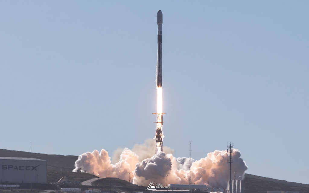
Mission 1 was the first step. SmartIR has since taken its graphene radiator to low Earth orbit, launching on SpaceX’s Transporter-12 in January 2025 and on Transporter-13 in March 2025.
What we took from it
Hardware for a flight test is an exercise in restraint. The best decisions on this board were the ones that removed things: fewer wires, fewer parts, no moving configuration, and a power-up state that does nothing until it is told to. The same instincts shape everything we build at Ivory Electronics, whether it is headed for the stratosphere or a lab bench.
If you are developing a novel device that needs electronics to drive it, test it or take somewhere unusual, we would be glad to help. Find us at www.ivory-electronics.com