Designing an integrated instrument for the teaching and research lab
In many labs, an electrochemistry experiment still means a familiar scene: a bench supply, a multimeter or two, a conductivity meter, a thermometer, and a tangle of leads connecting them. Every instrument has its own display, its own quirks and its own way of recording (or not recording) data. We were asked to fold that bench into one instrument for university-level teaching and research work. The electronics are designed, built and validated on the bench. Here is what went into it, and why it was harder than it looks.
One box, many jobs
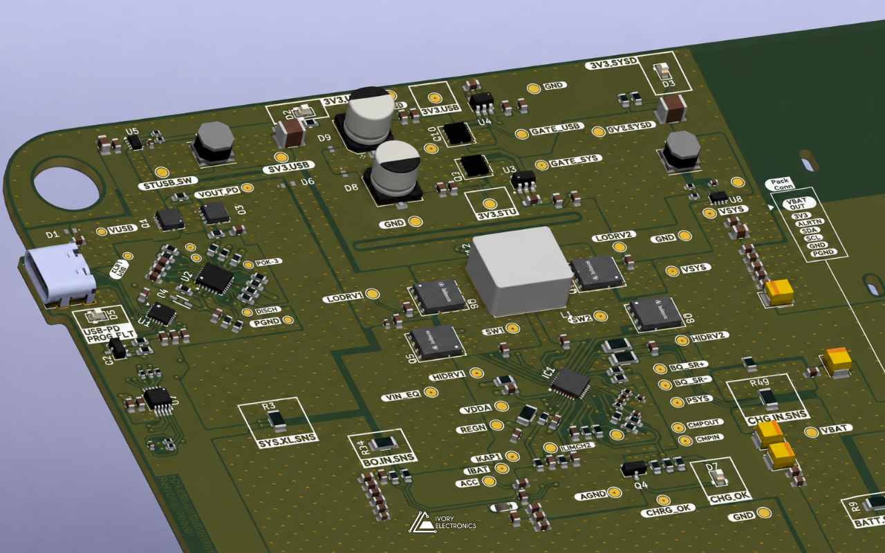
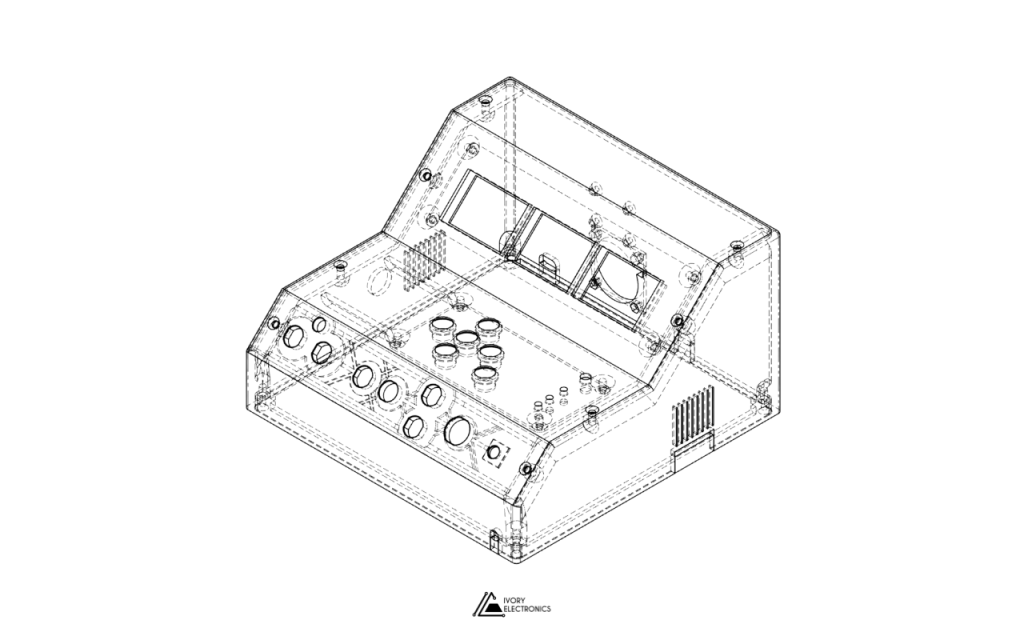
The instrument brings together, on a single two-layer board:
- A protected power output: a 12 V output with a current limit set from firmware, plus independent overcurrent detection.
- Measurement channels: current, voltage, electrolytic conductivity and temperature, digitised by a 16-bit, 8-channel ADC referenced to precision voltage references.
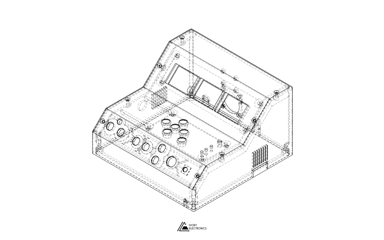
- A self-contained user interface: three graphic displays, six navigation keys, RGB status indicators, an alert buzzer and an illuminated power button.
- Data handling: a Wi-Fi and Bluetooth LE capable microcontroller, a full-size SD card, EEPROM and a battery-backed real-time clock, so every measurement can be time-stamped and kept.
Each function is textbook on its own. Making them coexist on one board, sharing one supply, is where the engineering happens.
Hurdle 1: Mixed-signal on two layers
A two-layer board keeps cost down, but it removes the luxury of a solid ground plane under everything. Here, a power stage that can carry hundreds of milliamps shares the board with millivolt-level measurement signals. We split the design into three ground domains (analog, digital and power) and joined them deliberately with net ties, so return currents from the output stage and the digital logic do not flow through the analog reference. The design is organised into digital and analogue sections, keeping the sensitive front ends away from the power paths.
Power comes in over USB-C Power Delivery, negotiated at 12 V, with a TVS clamp at the input and a supply-health signal back to the controller. From there, dedicated regulators generate the logic rails, separate analog rails and a symmetric ± supply for the circuits that need to swing both sides of ground.
Hurdle 2: A current limit that has to survive itself
Electrochemical cells are unforgiving loads: an electrode short or a misconnected lead can ask for far more current than the experiment needs. The output therefore has a real current clamp: a sense resistor, an error amplifier and a MOSFET that regulates linearly to hold the current at a limit that the firmware sets through a DAC. A separate comparator watches for overload and raises a digital flag, which firmware turns into an audible alarm.
The catch with linear regulation is heat. At the limit, the MOSFET absorbs the entire difference between the supply and the load voltage. Semiconductor vendors warn that linear-mode operation is exactly where MOSFETs are most fragile: below the zero-temperature-coefficient point, a hotter region of the die draws more current and gets hotter still, which can end in thermal runaway. Nexperia’s application note on the subject shows one device whose usable current at 20 V dropped by about 75% compared with the simple theoretical figure. We designed a custom footprint so that the MOSFET could be pressed against an aluminium heat-spreading slab, instead of relying on copper area alone.
Hurdle 3: Measuring conductivity without destroying the sample
Conductivity looks like a resistance measurement, but DC is the wrong tool. As Analog Devices puts it, applying DC to the electrodes lets ions accumulate on their surfaces, causing “polarization, measurement errors, and damage to the electrode.” The same article points out two more traps: a single cell can present anything from about 30 Ω in seawater to 1 MΩ in pure water, and conductivity changes by up to 4% per °C.
Our conductivity channel drives the probe with an AC excitation derived from an on-board oscillator, conditions the result with op-amps powered from the symmetric supply, and hands a clean signal to the ADC. Because temperature matters so much, the instrument also has an NTC temperature channel, so readings can be compensated in firmware rather than taken at face value.
Hurdle 4: Current measurement in both directions
In electrochemistry, current direction carries meaning. The ammeter channel uses a low-value shunt and a current-sense amplifier biased around a precision mid-scale reference, so current in either direction lands inside the ADC’s input range. The channel is fused through an external, user-replaceable fuse holder, so a blown fuse is a quick swap rather than a repair job.
Usability: an instrument, not a dev board
A lab instrument is judged by the person using it, not by the person who designed it. That shaped several decisions:
- Three screens, not one menu. Related readings stay visible side by side instead of being buried in pages.
- Soft power control. A small dedicated controller handles the illuminated power button, switches the main rail through a high-side MOSFET, and receives confirmation once the 3.3 V rail is up, so power sequencing is controlled rather than left to a mechanical switch.
- Feedback you can see and hear. RGB status lighting shows system and error states, and the buzzer flags events such as an overcurrent trip.
- Data that leaves the bench. SD logging with real-time-clock timestamps, plus wireless connectivity available to the firmware.
Built to be brought up, and serviced
Two-layer and cost-conscious does not have to mean hard to debug. The board carries 45 labelled test points across the supply rails, references and signal chain, plus jumpers on the main supply rails for bring-up. A JTAG header and an internal debug UART give firmware engineers full visibility. When something needs checking during bring-up or in the field, the answer is a probe tip away.
How we work
As with all our projects, the design lives in KiCad as hierarchical sheets, one per functional block, under Git version control. Datasheets and reference designs sit in the repository next to the schematic, and design calculations (gains, thresholds, reference levels) are written onto the schematic itself, so the reasoning travels with the design.
The result
The boards have been manufactured and validated on the bench: power negotiation, regulated rails, the current-limited output, and the measurement, display and logging chain all working together.
If you have a lab workflow that deserves better than a pile of separate instruments, or any measurement problem that mixes precision analog, power and a usable interface, we would like to hear about it. Visit www.ivory-electronics.com