Scanning a capacitive sensor array with a capacitance-to-digital converter, sixteen analog switches and a lot of respect for parasitics
A fingertip hovering over a surface. A drop of liquid spreading across a membrane. A thin film flexing under load. Each of these changes a capacitance, often by a tiny fraction of a picofarad. Measure one capacitor, and you have a sensor. Measure a whole grid of them, and you have an image of something you cannot see. That is the promise of a capacitive sensor array.
That is what our capacitive sensor array test bench does. It pairs a precision capacitance-to-digital converter (CDC) with a matrix of analog switches so that every crossing point of a row-and-column electrode array can be measured, one at a time, with laboratory-grade resolution. Here is how it works, and why the chip at its heart deserves more attention than it gets.
Why the AD7745 is a remarkable chip
Most engineers who need to measure capacitance reach for an RC timing trick or a touch controller. Both work well enough for a button. Neither is a measuring instrument. The Analog Devices AD7745 is. Straight from its datasheet:
- 24-bit sigma-delta conversion, built on a second-order charge-balancing modulator and a third-order digital filter, with up to 21 bits of effective resolution.
- Attofarad-level noise: about 5.4 aF rms at a 62 ms conversion time. One attofarad is 10⁻¹⁸ F.
- ±4 fF absolute accuracy, factory-calibrated, with ±0.01% linearity.
- A ±4 pF measurement range riding on up to 17 pF of fixed, non-changing capacitance, which an on-chip programmable offset DAC (the CAPDAC) cancels.
- Built-in extras: an on-chip temperature sensor (0.1 °C resolution, ±2 °C accuracy), a 24-bit voltage input channel, simultaneous 50 Hz and 60 Hz rejection at the 16 Hz update rate, and a simple I²C interface. It runs from a single 2.7 V to 5.25 V supply at about 0.7 mA.
The line that matters most for arrays, though, is easy to miss. The AD7745 is designed for floating capacitive sensors, where neither plate is tied to ground, and it tolerates substantial parasitic capacitance from its pins to ground: up to 60 pF on the capacitive input and 100 pF on the excitation pins. Hold that thought.
From one capacitor to a capacitive sensor array
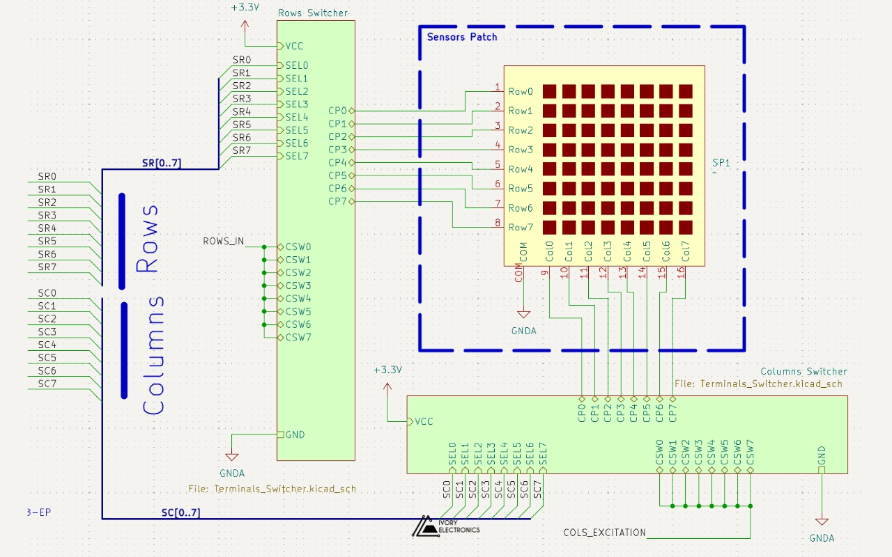
A row-and-column electrode array is a natural fit for a floating-sensor CDC. Every place a row crosses a column forms a small capacitor. Drive a column with the CDC’s 32 kHz excitation, listen on a row with its capacitive input, and you are measuring exactly one crossing point: a mutual-capacitance measurement.
The challenge is that a matrix is full of capacitors you do not want to measure. Every other row and column couples to the selected pair, and the long traces add their own parasitics. Leave the unused electrodes floating and they carry signal from one crossing to another, blurring the image.
The trick: switch, and ground everything else
Our test bench gives every row and every column its own single-pole, double-throw (SPDT) analog switch, sixteen in all. Each switch has two positions:
- Selected: a column is routed to the CDC’s excitation output, or a row to its capacitive input.
- Not selected: the electrode is tied to analog ground.
That second position is where the thought we held earlier pays off. Grounding every unselected electrode turns the stray coupling between the selected pair and its neighbours into capacitance to ground, and capacitance to ground is exactly what the AD7745 is designed to tolerate. The unused lines stop behaving as crosstalk paths and start behaving as a shield. The converter sees only the crossing point we chose.
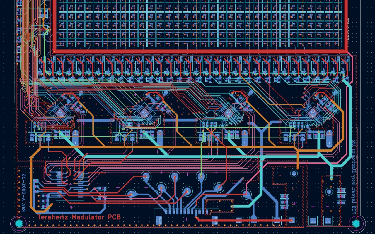
The switches are driven by SPI port expanders, not directly by the microcontroller. SPI keeps selection changes fast, and it keeps the microcontroller’s pins free for everything else. A Wi-Fi and Bluetooth-capable microcontroller orchestrates the scan, reads the CDC over I²C, and can hand results to a host or an external wireless link. It is the same row-and-column addressing idea we used to drive thousands of pixels in our active-matrix electronics for terahertz graphene surfaces, turned around to measure instead of drive.
Guarding the femtofarads in a capacitive sensor array
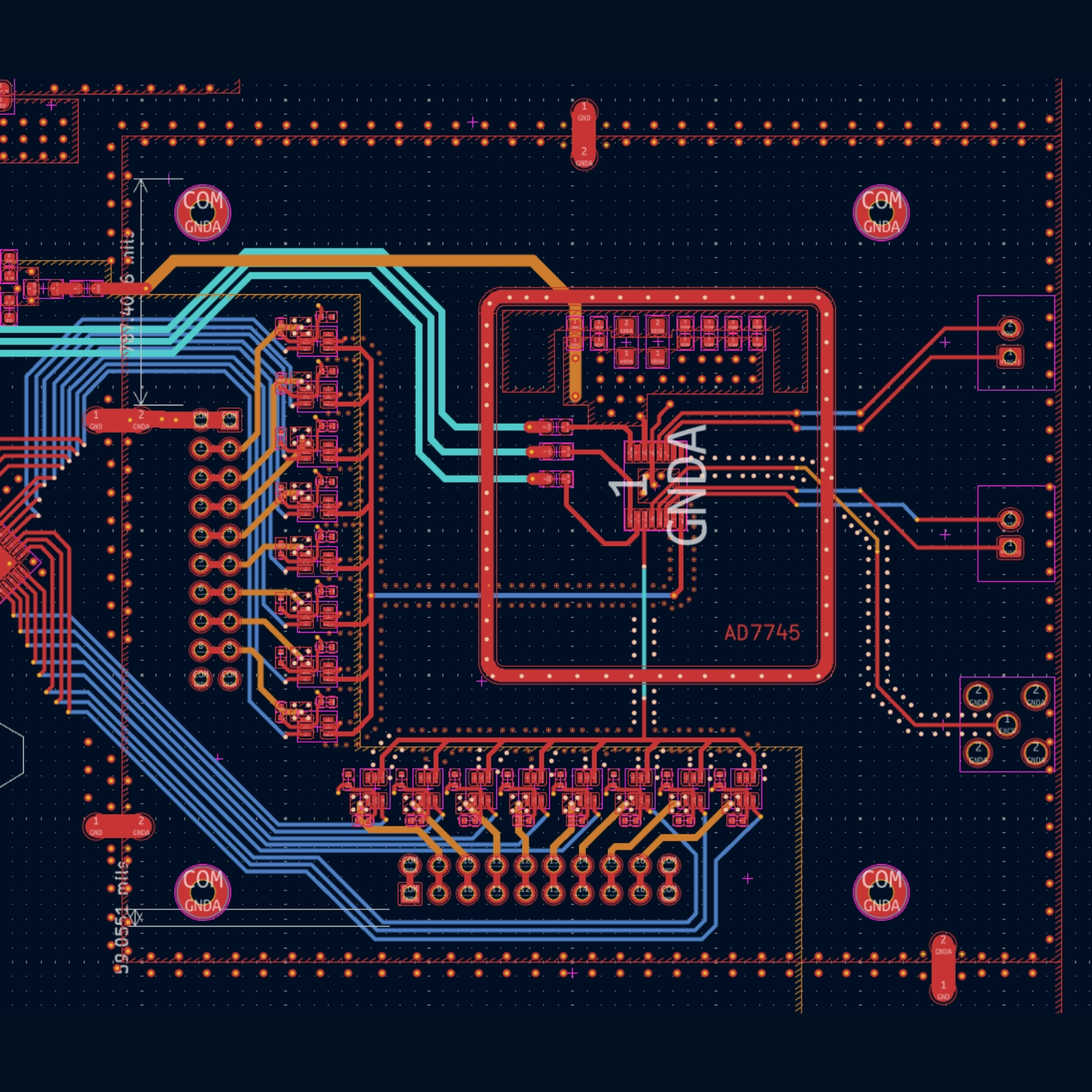
At attofarad noise levels, the PCB itself is part of the sensor. The board reflects that:
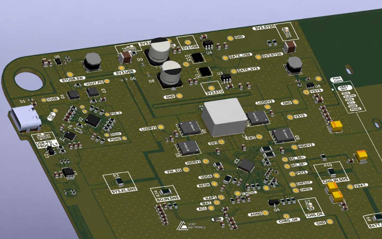
- A six-layer stack-up with dedicated planes, more than 1,100 vias, and a separate analog ground joined to the digital ground at defined points through net ties.
- A quiet analog supply: a low-noise linear regulator followed by LC filtering, with generous local decoupling at the CDC.
- Shielding options: a footprint for an EMI shield can over the converter section, and an SMA coaxial connector on board.
- Flexible power: a 9–15 V adapter input or a single lithium-ion cell, with a boost converter providing 5 V for an external radio link.
The honest trade-off: precision versus speed
There is no free lunch. The AD7745 converts one capacitor at a time, at update rates between 10 Hz and 90 Hz. Even at the fastest setting, that is roughly 11 ms per conversion, so scanning an 8 × 8 matrix, 64 crossing points, takes the better part of a second. Choose a slower, quieter setting and each frame takes several seconds.
For many applications that is perfectly fine: the phenomena being measured change slowly, and resolution matters far more than frame rate. Where speed does matter, the test bench is exactly the place to explore the options: scanning only a region of interest, adapting the conversion time to the signal, or splitting the array across several converters working in parallel. That is what a test bench is for: learning the limits before committing a product to them.
Where could a capacitive sensor array go?
The datasheet lists pressure, position, level, flow and humidity sensing, and impurity detection among the AD7745’s target applications. Put that capability behind a switch matrix and the list grows:
- Tactile and pressure-mapping surfaces that feel where, and how hard, they are touched.
- Proximity and gesture sensing through a non-conductive panel.
- Liquid level, spreading and contamination across a surface, rather than at a single point.
- Quality inspection of thin films and printed electronics, one electrode crossing at a time.
And the ones we have not thought of yet. If a phenomenon moves charge around, a capacitive array can probably see it. What would you point one at?
Built as a platform
The board has been built and is our development platform for capacitive scanning routines, complete with a JTAG debug port, UART access and status indication, so firmware can be iterated quickly. It is a good example of how we like to approach new sensing problems at Ivory Electronics, just as we did with our all-in-one electrochemistry bench: pick the right converter, respect the physics of the parasitics, and build a platform that makes the hard questions easy to ask.
Working on capacitive sensing, sensor arrays or a custom measurement system? Let’s talk: www.ivory-electronics.com.
Ivory Electronics: Laying out ideas, tracing innovation.