Smart battery evaluation on our terms: a MAX17320 evaluation board, from schematic to spot weld
A customer needed a custom lithium-ion battery pack with a proper brain: accurate state-of-charge, full protection and authentication, all living inside the pack. The obvious first step is to buy the vendor’s MAX17320 evaluation board and start experimenting. At the time we checked, Mouser listed it at 135 USD plus VAT, with three units in stock. That is not a crisis, but it is not a comfortable position either when a prototype is urgent, you need more than one board, and the kit’s layout has nothing to do with your pack.
So we did what we usually do. We designed our own MAX17320 evaluation board, shaped it around the pack, and then built the pack itself, spot-welding the cells by hand. It was a daunting job, and a very rewarding one.
Why the MAX17320
The Analog Devices MAX17320 is a pack-side fuel gauge and protector for 2S to 4S lithium-ion and lithium-polymer batteries. It packs a lot into one IC:
- Fuel gauging: the ModelGauge m5 EZ algorithm reports state of charge, remaining capacity, time-to-empty and time-to-full, battery age and cycle forecasting.
- Protection: temperature-dependent overvoltage, overcharge, overdischarge and short-circuit current, over- and under-temperature, undervoltage, and detection of internal self-discharge in a cell.
- Pack housekeeping: internal cell balancing, four thermistor inputs with ±1 °C accuracy, JEITA charging prescriptions, pushbutton wake-up, and 84 bytes of non-volatile memory for history logging and user data.
- Measurement without calibration: precision current, voltage, power and time measurement, exposed through an SBS 1.1-compatible register set, at 38 µA of quiescent current with the protection FETs enabled.
- Security: SHA-256 challenge-response authentication, so a host can tell a genuine pack from a counterfeit.
First hurdle: the variant maze
Before a single trace is routed, you have to pick the right part, and the MAX17320 comes in 20 orderable part numbers, counting tape-and-reel versions. They differ in three independent ways: package (a 4 × 4 mm 24-pin TQFN for the G-series, a 30-bump WLP for the X-series), host interface (I²C or 1-Wire), and whether SHA-256 authentication is present. The G-series always includes authentication. In the X-series it depends on the suffix, and it is easy to assume otherwise: the X20, for example, is I²C and WLP but has no SHA-256.
We documented the full matrix before starting the schematic, and chose the MAX17320G22+: I²C, SHA-256, and a TQFN package, which is far friendlier to prototype assembly and rework than a wafer-level package. Getting this wrong means a respin, because the two packages share no footprint.
A tour of the MAX17320 evaluation board
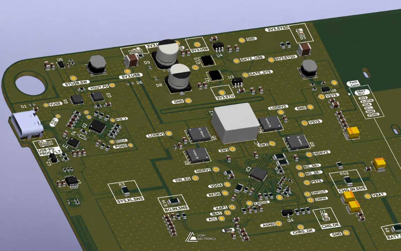
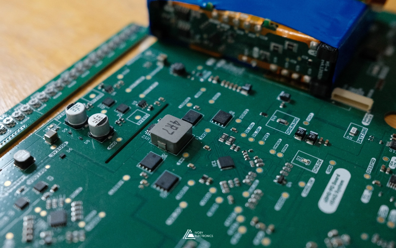
The result is a four-layer, 80 × 70 mm board. It follows the vendor’s reference guidance where that matters and departs from it where the customer’s pack needed something different.
Power path. Protection is handled by two N-channel MOSFETs in a common-drain, back-to-back arrangement on the positive rail between the cells and the system terminal, so the IC can block charge and discharge independently. Each gate is driven by the IC’s CHG and DIS outputs through a series resistor, with Schottky clamps on the drive and pack-sense nodes.
Current sensing. A 5 mΩ sense resistor sits in the negative path. That is the same value the vendor kit uses for its default ±10 A range, and a smaller resistor extends the range if a future pack needs it.
Cell sensing. Every cell tap reaches the IC through a 49.9 Ω series resistor, with 10 nF filter capacitors across adjacent taps. This forms a differential RC filter on each cell voltage, keeping noise out of the measurement. Jumpers configure the board for 2S, 3S or 4S packs, so one design covers the whole range the chip supports.
Secondary protection. Primary protection is only as good as its FETs. The MAX17320 has a permanent-failure output (PFAIL) intended to act when it detects a failed primary FET. We connected it through a small N-channel MOSFET to a three-terminal battery protector: a surface-mount device with a fuse element and an integrated heater. When PFAIL fires, the heater blows the fuse, and the pack is permanently isolated. A solder jumper selects between this path and the datasheet’s recommended termination for when the feature is not used.
Temperature. All four thermistor channels are populated with 10 kΩ NTCs, so temperature can be sensed at several points of the pack, not just one.
Robust communications. The I²C lines and the alert output each pass through a 100 Ω series resistor with a 5.6 V Zener clamp to ground, and spark gaps guard the exposed terminals. A pack is a device that gets plugged, unplugged and handled, and its communication pins face the outside world.
Configuration and access. A header configures the zero-volt charging path, which runs through a 1 W resistor. A pushbutton provides wake-up, an LED shows the alert state, and the always-on 3.4 V LDO output is brought to a test point. Large loop test points on every cell tap, the pack terminals and the system terminals make probing and connecting the real pack straightforward.
Vendor kit versus a custom MAX17320 evaluation board
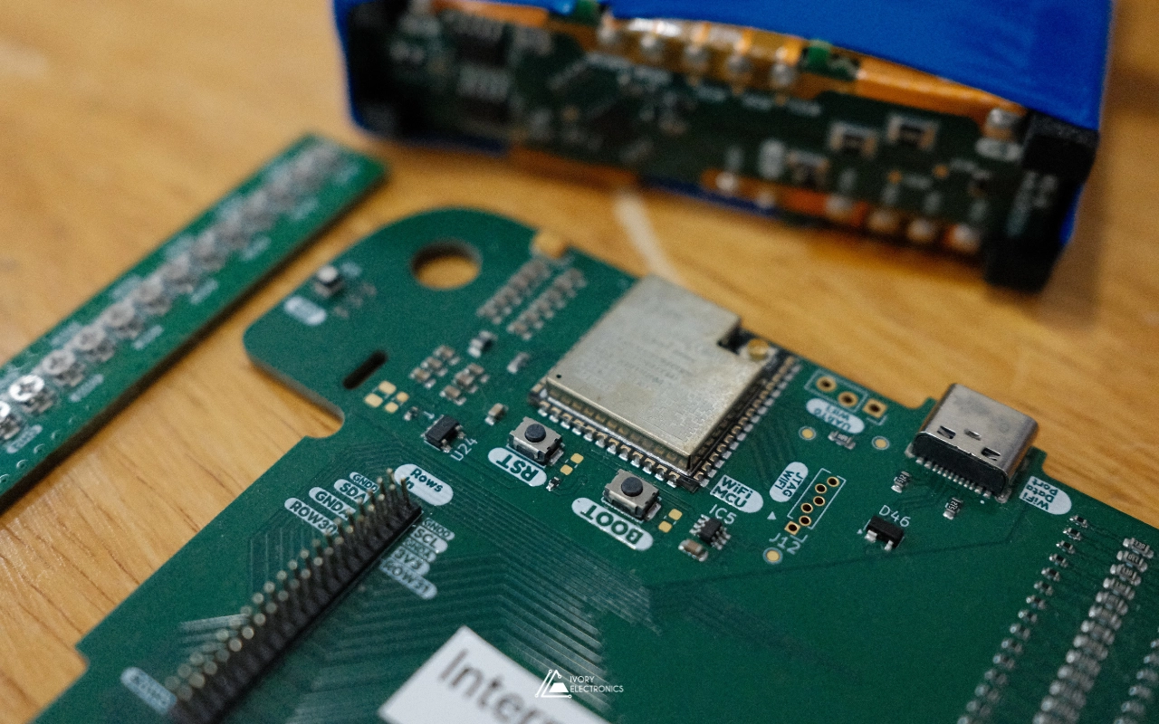
Vendor evaluation kits are excellent at what they are for: showing that a chip works. The official MAX17320 kit is a fully assembled board with an integrated USB interface and a Windows GUI that needs .NET. For our situation, a purpose-built board won on several counts:
- Availability: we could build as many as we needed, when we needed them, instead of waiting on a low-stock distributor line.
- Fit: the terminals, cell taps and test points match the customer’s pack, so evaluation happens in conditions much closer to the final product.
- Openness: a standard I²C header means any host can talk to the gauge, whether that is our own tools, the customer’s firmware or a logic analyser, with no dependency on one operating system.
- Knowledge: designing the board forces you to understand every protection path, which pays off when you move to the production pack.
That is the quiet advantage of custom evaluation hardware: it is not a detour on the way to a product, it is the first draft of it.
Building the pack: 18650s, nickel and patience
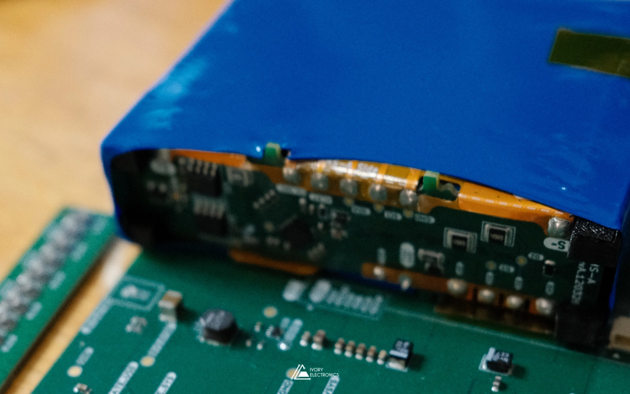
A gauge needs a battery, and a custom pack needs building. We assembled a 3S pack of 18650 cells using 0.1 mm nickel strip and a portable FNIRSI SWM-10 spot welder.
Why weld rather than solder? Soldering puts well over 300 °C into the cell terminal. Resistance spot welding delivers a very short, high-current pulse, typically milliseconds, that fuses strip and terminal locally while keeping heat away from the cell’s internals. The technique is simple to describe and unforgiving to execute:
- Consistency is everything. Electrode pressure, alignment and pulse energy all affect every weld. Too little energy gives a joint that looks fine and peels off, too much can mark or damage the terminal. Pull tests on scrap strip are how you find the settings.
- Series means stakes. In a 3S pack, a strip in the wrong place is a short circuit across a charged cell. Layout, insulation between groups and a deliberate welding order matter as much as the welds themselves.
- Balance leads are part of the design. Each series node needs its own tap back to the gauge, and those taps feed the filtered cell-sense inputs described above.
It is slow, careful work, and there is real satisfaction in seeing a pack you welded yourself report its first accurate state of charge.
The result: a validated MAX17320 evaluation board
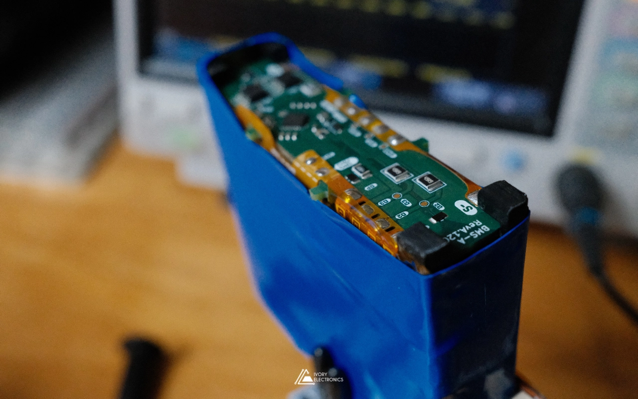
The MAX17320 evaluation board has been built and validated with the finished pack, with fuel gauging, protection and communication all working. The customer got a tailored evaluation platform and a real pack to develop against, without waiting on a low-stock distributor line.
Flashing the brain
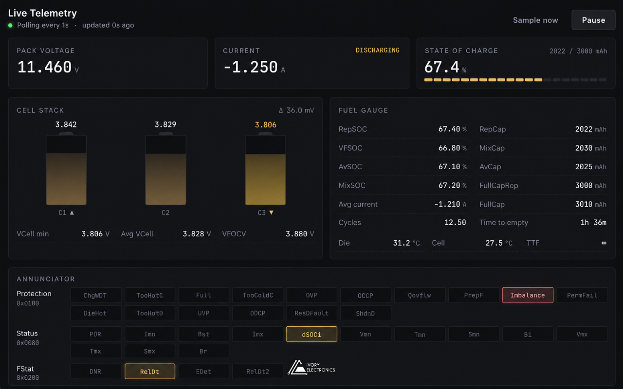
There is one more catch with this chip family. According to the vendor’s evaluation-kit documentation, the non-volatile configuration memory can be updated only seven times. That makes every flash cycle precious, and it makes careful, verified programming essential. We built a tool for exactly that: a compact NVM flasher based on an ESP32-C3, paired with web-based software for reading registers and flashing configurations quickly and safely. Read the full story in Safely Configuring a Battery Fuel Gauge IC.
Need a battery management design, a custom pack or evaluation hardware that fits your product rather than a catalogue? Talk to us at www.ivory-electronics.com.
Ivory Electronics: Laying out ideas, tracing innovation.