How we built a compact board that measures where every amp goes
When a battery-powered system misbehaves, the first question is simple: where is the current going? Answering it usually means a multimeter in series and a lot of guesswork. A clamp meter rarely helps, because it cannot resolve small loads. Multi-channel current monitoring answers that question directly.
We designed a compact controller board for multi-channel current monitoring. It reads several independent current channels and sends the data to a wireless-capable microcontroller. It also has enough interfaces to sit inside a larger system. The boards are built and validated on the bench. Below are the design decisions that mattered most.
Multi-channel current monitoring on one board
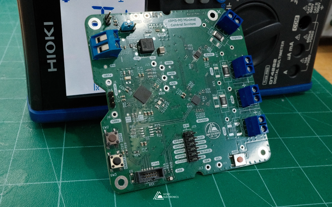
Everything sits on a single four-layer board:
- Multi-channel current monitoring: three channels on a shared digital power monitor, plus one dedicated high-resolution channel. Each one measures shunt current and bus voltage, and reports power over a digital bus.
- A wide-input power stage: a buck regulator that runs from the monitored supply itself. It covers a wide input range and produces a clean 3.3 V logic rail.
- A wireless-capable microcontroller: with Wi-Fi and native USB, placed directly on the board rather than as a plug-in module.
- Storage and interfaces: non-volatile memory for calibration data, and broken-out I²C, SPI, UART and GPIO. Power-good and alert lines connect the board to the rest of the system.
Getting a reading is simple. Getting a trustworthy one from four channels, at several amps, beside a switching regulator, took most of the design effort.
Hurdle 1: Choosing the shunt
Every current channel starts with a sense resistor, and its value is always a compromise. A larger value gives a bigger signal and better resolution. It also steals voltage from the load and turns it into heat. Dissipation grows with the square of the current, so at several amps even a few milliohms matter.
A smaller value runs cooler, but it pushes the signal toward the monitor’s offset and noise floor. Digital current monitors also accept only a small full-scale shunt voltage. The resistor must keep the peak current inside that window.
Package size is part of the same decision. Small chip resistors that work at low current become a reliability risk at several amps. So each channel uses a large-format power resistor with plenty of thermal margin. Each channel also has an alternate footprint for a through-hole shunt. Changing the measurement range is a job for a soldering iron, not a board respin.
Hurdle 2: Filtering without adding error
Real current waveforms are noisy. Switching regulators, motors and PWM loads all put ripple on the line. A differential RC filter at the monitor inputs is the standard fix.
The problem is input bias current. Current-sense monitors draw a small current through their input pins. Any series resistor turns that current into an offset. The bias current also differs between the two inputs and shifts with conditions, so it shows up as gain error too. Texas Instruments explains this in its application note on current-sense amplifiers with input series resistors.
Our filters keep the series resistance small and let the capacitance do most of the work. The noise comes down without trading away accuracy.
Hurdle 3: A switching regulator next to millivolt signals
The controller runs from the same supply it measures, so efficiency matters. A buck regulator is the right choice, but it is also the noisiest part on the board. For multi-channel current monitoring, that noise sits right beside signals in the microvolt-to-millivolt range. The four-layer stack-up gives return currents a short, predictable path on the inner layers. They stay away from the measurement front ends.
The power stage can also be brought up on its own. Solder jumpers separate the input, the enable control and the 3.3 V output. Test points sit on the input, the switch node, the output and the enable line. We can check the regulator in isolation before the rest of the board sees power.
Hurdle 4: Many devices, one bus
The current monitors and the configuration memory all share one digital bus. Each device has solder-jumper address selection instead of a hard-wired address. Addresses can change without a redesign, and the board can share its bus with other devices in a larger system. The memory also has a write-protect jumper, so calibration data cannot be overwritten by accident.
Multi-channel current monitoring, designed for the integrator
Most of the time, this board lives inside someone else’s system. So we designed it around wiring, installation and day-to-day use:
- Screw terminals for current paths. Several amps should never flow through a pin header, so every sense channel lands on a screw terminal.
- Visible status. An RGB indicator and a power LED show the board’s state from across the room.
- Separate user and developer controls. An on/off button for everyday use, with boot and reset buttons kept for firmware work.
- Mounting built in. Four M3 holes let it bolt into an enclosure or a larger assembly.
From first power-up to validated
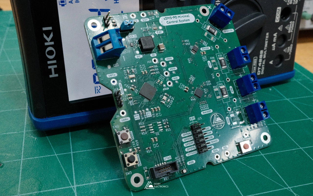
The board is laid out for staged bring-up rather than a single, all-at-once power-on. Jumpers on the power path let the regulator run alone first. The microcontroller comes next, then each device on the bus. Labelled test points on the rails and communication lines make every step measurable.
For firmware, a JTAG header gives full on-chip debugging. The serial port sits behind its own jumper, so it can be disconnected when another device needs those lines. Faults stay isolated to one block instead of hiding behind the whole board.
Where multi-channel current monitoring fits
Every stage has been built and checked on the bench: the wide-input power stage, the microcontroller, all four current channels, and the storage and interfaces. The board now delivers dependable multi-channel current monitoring in a small footprint.
That makes it a good match for battery packs such as our custom MAX17320 pack, power distribution units like our single-cable power board, test rigs and any product that needs a per-rail power budget.
Need multi-channel current monitoring in your own system, or have a problem that mixes precision analog, power and firmware? We would like to hear about it. Visit www.ivory-electronics.com.
Ivory Electronics: Laying out ideas, tracing innovation.